3d 4 ways of translating drawings into objects
Line art, such as logos, family unit crests, text or numbers, cartoon characters, and fifty-fifty sketches can be quickly and easily translated into 3D models in Matrix for use in a variety of jewelry designs. Depending on the skill of the user, the end use of the artwork, and the requirements of the model, you may wish to select one of the 3 following methods, or mix these methods for optimal effect.
A Study of 3 Methods for
Translating Line Fine art into 3D Models in Matrix
The iii methods include (1) extruding closed curves to create a flat-topped blueprint that can be used every bit an engraving or relief element; (ii) inputting airtight curves into Matrix Art to employ various cross-department shapes to the line art and complete a mesh model of the prototype, or (3) surface modeling, using a variety of Surface menu commands, to create a true 3-D relief model of the artwork. Each of these methods has its advantages, and each may be used at unlike times by the novice or advanced user depending on the desired result.
-
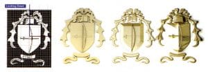
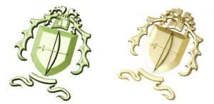
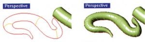
- (Fifty-R) Original line art image
Method I – Extrude Planar Curves; Method 2 – Matrix Art; Method 3 – Surface Modeling.
Getting Started
Each method starts with the Place Background Bitmap tool. Select the line art you lot wish to use from the folder on your hard drive. Then, working in the Looking Down viewport, identify the upper left-mitt corner of the image file at well-nigh the location and size you'll want it for the finished design. The bitmap will form a rectangle in the same attribute ratio (summit to width) of the original image. That way, the bitmap cannot be skewed equally you place it. Locate the lower correct-hand corner of the bitmap at the size and location desired by clicking once more in the Looking Down viewport, and the bitmap will appear onscreen.
Now, using the Curve tools, carefully trace the line art design. Information technology is a good idea, as you're doing then, to use layer colors strategically. For instance, if you trace each different shape in the line art design on a different layer color, you can right-click on the colour to select all of the shapes on that layer, rather than trying to do a region-select or hold down shift for a multiple-choice in the viewports.
-
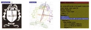
- (one) Place Background Bitmap; (2) Trace with Curve Tools, using Layer Colour strategically;
(3) Check that each curve is "closed" and "valid" with Object Information.
It is also very of import that yous apply the Cease O-Snap to connect the ends of all of the curves that you used to make a single shape, and, when the shape is consummate, Join those curves to create a single, airtight curve. For the starting time two methods – extruding closed curves and using Matrix Fine art – you'll demand closed curves to be successful. To cheque a curve that yous drew to ensure that information technology is "airtight" and "valid", click Object Information and bank check the report.
Extruding Closed Curves: The easiest method for creating 3D models from line art in Matrix is to utilise the From Planar Curves command, which is found in the Solids menu, to extrude the closed curves. To make up one's mind how bill of fare, to extrude the airtight curves. To determine how best to select your curves for the extrusion control, have a look at your line art: you'll now demand to make some design decisions near how you want to use this image to enhance your model.
For example, you can create a simple relief image, where each shape in the design is at a different height. To reach this, select the parts of the pattern you want at the same height and click From Planar Curves. If you'll be using this design as a cutter, or if you lot'll need to Boolean Marriage it to your model for use in a growing machine that can't accept intersecting solids, it's a good thought to use the "Both Sides = Yes" option that is available in the Command line during this command. That style, your model volition not be "coplanar" and will Boolean successfully.
-
- (ane) Extrude curves 1-by-i to the top desired for the design; or,
(2) select 2 closed curves together, one fully inside the other, to create negative space in the design.
Enter the thickness yous want for the pattern into the Command line, and press Enter. Echo, using a new thickness (taller) for the adjacent set of shapes, and go along until the design is complete. Or, to create "negative space" in the extruded pattern, select two closed curves – one that is fully within the other – and use the Form Planar Curves command on them together. This will create holes in the pattern that will add visual interest to your final model.
To add this line art to a model, you may wish to identify information technology on superlative of a ring to create a relief pattern – using Boolean Union only if the model volition be grown with a machine that cannot handle intersecting solids. Alternately, subsequently Boolean Unioning the blueprint together, Boolean Divergence it from the top of a ring, creating an engraving of the blueprint.
-
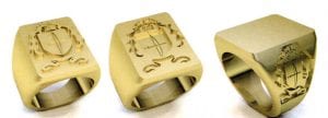
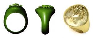
- (ane) Boolean Union the design to the ring for growing; (2) Boolean Departure to create an engraving;
(3) Boolean Intersection with side console Cap to create shield design
Finally, you may wish to identify the design on a curved surface – such as the side shield of a signet band. In that example, use closed, flat curves fatigued in the Side View viewport to create the shape of the shield. Then, using the Project control, apply these curves to the side of the signet band. Identify the ring and the curves representing the shield into appropriate boxes in Matrix'south Surface Pullback tool, assign a depth and bevel shape, and employ the Cap command to create a solid "cap" surface in the shape of the shield. Position the blueprint then that information technology fully intersects the shield, and, after Boolean Unioning the design together, run a Boolean Intersection on the design and the cap you lot only created.
Creating a Mesh
Alternately, you may prefer a dissimilar contour shape for each function of your design instead of the flat blocks created with Extrude Planar Curves. Inputting the curves into Matrix Art is a quick and easy way to achieve this. The mesh file output by Matrix Art can likewise be applied to different-shaped surfaces using the Curve command – a trick nosotros'll demonstrate later in this article.
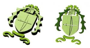
The layer colour of each closed bend making up your blueprint is even more important to consider when inputting your model into Matrix Art. Since the layer structure is hierarchical in this builder, information technology's important to identify the lower parts of the epitome onto the lower layer colors (the shield as the groundwork for the bow and sword, for example) and the college parts of the image (the bow and sword, in this case), onto college layer colors.
With all of the curves input into Matrix Fine art, employ the Layers menu in the builder to select a color to work on. Then, click on Load Profile to utilize a cross-section shape to that layer. You lot may too assign a height to each surface on the same layer color. Finally, to change the interaction between overlapping surfaces, click on the Layers carte du jour where the dominant (higher in the bill of fare) color, which should exist selected in pink, lines upwards with the cavalcade of its subordinate (lower) color until the human relationship between the 2 is correct. Click and Create Mesh to create a single mesh surface from the design.
Or, to create mesh surfaces that can be manipulated independently of ane another, input one or several curves at ane into Matrix Fine art and perform separate Create Mesh operations for each set up. That way, you can reposition each office of the mesh separately to create the look you lot want.
Surface Modeling: The almost advanced way of translating line fine art into a 3D model uses commands in the Surface carte du jour to physically model each element in the pattern. In this case, the curves are traced in the same way equally above; still, depending on the Surface carte tool y'all'll employ with them, you may demand open curves rather than closed, to complete the image. The user must select the best modeling strategy to complete each chemical element in the blueprint based upon the look you lot want.
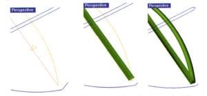
For example, to create the bow, we'll input a single, straight polyline representing the bow into Profile Placer much the same way we would a ring rail. Select a profile shape for the bow and use the dimension sliders and Set Profile to place a profile along the track. Sweep 1 – with the straight line as the track curve and the profile every bit the cross-section – is the surface tool to complete this office of the design. Use Cap Planar to close this model.
-
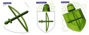
- (one) Loft Sword; (2) Revolve helmet; (3) Rail Revolve Shield
To consummate the bow, Pipage is a Solid menu control that will utilize a circular profile to whatever curve, creating a "pipe" effect. Only select an open curve drawn to correspond the bow string, and click on Pipe. Assign the same dimension for one finish and the other for continuity'south sake. Again, make sure the pipage is "capped".
To create an angled profile with a flat pinnacle for the sword, select the closed curve used to depict it and Offset it a small distance to the outside. Select the inner curve and elevate it up in space to the elevation desired for the sword. Loft between the two curves, making sure the seam signal arrows are lined upwards on a long "straightaway" of the blueprint, and Cap.
-
- (ane) Depict Profile Curve; (2) Carve up closed bend at midpoint and utilize Orient 2 Points to place contour betwixt Midpoints of split curves;
(3) Sweep 2 with "Bespeak" option on either stop and profile at eye.
Revolve is a fun tool to achieve a true 3D object from a single profile revolved around its eye point. Select the closed bend of the helmet and click Revolve. To assign the centrality of revolution, click on the acme and lesser of the helmet, drawing a straight line through its heart. If the revolved surface is besides tall for the balance of your design, select it and utilise the Calibration 1D tool to shrink it in the Through Finger viewport to the height required for the blueprint.
A like tool, Rail Revolve, works in a related fashion; simply the profile is revolved along whatsoever shape of bend, instead of in a circumvolve. To use this tool to its total advantage, try it out on the shield. Describe a profile that starts along the midpoint of one one-half of the shield curve and extends up in the Through Finger viewport in the shape you desire for the tiptop of the shield. Select this profile and click Rail Revolve. The rail curve is the shield, and the revolve centrality is straight down from the top of the contour curve:
-
- (ane) Place additional profiles using Orient 2 Points and Copy – locate them where the two curves curve and bow dramatically;
(2) Sweep two, with Bespeak selection on each cease and arc profiles in betwixt.
To create ribbons beneath the shield, dissever the closed curves y'all've created the "long style" this fourth dimension – at the midpoint of each short cease – creating two halves: top and bottom. In the Through Finger viewport, draw an Arc Management. Using the Orient two Points command with "Re-create" turned on; assign the ends of the arc every bit the "Reference Points" and the MidPoints of the ribbon curves as the "Target Points". Place only ane copy at this location.
Now, using Sweep 2 – with the top and bottom of the ribbon as the rail curves – select the "Point" option and snap to one "End" where the two ribbon curves meet to indicate the first profile; the second contour is the arc you just placed; and the 3rd profile is also constitute with the "Indicate" choice at the other "Cease" of the two curves. The surface will appear. Cap it.
Complete the other two portions of the ribbon in the same style, using Orient two Points to place several copies of the arc profile along the rails curves, especially where they bow and curve dramatically, in order to keep the shape. The Nigh O-Snap should be used to place the first "target betoken" of the profile forth one rail, and the Perpendicular O-Snap should be used to place the other target bespeak then that information technology is perpendicular to the first. Use Sweep two forth each profile, with the "Point" pick enabled to select the Finish points of both curves – ane on either end – as the start and finish point of the surface. Cap to complete.
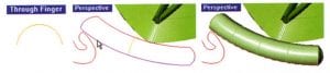
A similar technique can be used to sweep the vines. Only this time, let's depict a more interesting contour in the Through Finger viewport: one with a groove in the top to more than closely lucifer the original line fine art, which showed the veins running through the vine. Use Orient ii Points to place this profile along each open curve, using the above play a trick on of the Nigh O-Snap to place the outset target point and the Perpendicular O-Snap to place the second target betoken.
Applying a Mesh Design to a Surface
When the flat options offered above are not exactly what you need for your design, you have some other option, which tin can be run on any of the three models above as long as they are Mesh objects.
-
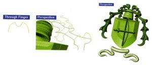
- (L-R) Curve Mesh Model in Through Finger and Side View viewports to utilise to curved surface on height of ring.
To transform a surface into a Mesh object, use the Utilities carte command Mesh. With your mesh design created, apply the Bend command to wrap information technology around the surface to which you want to employ it.
blankenshipcausubtlig.blogspot.com
Source: https://www.ganoksin.com/article/translating-line-art-3d-models-matrix/
Post a Comment for "3d 4 ways of translating drawings into objects"